The code for this part is available in this commit.
So, in the previous part we set up a test program to draw raw pixels on screen and started making our own tiny graphics API which currently only supports clearing the screen to a fixed color. Today our goal is to start actually rasterizing something, like a triangle!
Contents
Triangles
Wait, why specifically a triangle? Well, for the same reasons most graphics APIs have converged to using mostly triangles as well:
- Triangles are easy to rasterize
- Triangles are easy to uniquely interpolate attributes inside them
- The perspective image of a triangle is still a triangle
- Triangles can be used to approximate anything else to any desired degree of precision
Typically rasterizers also support drawing lines and individual points. We won't do that in this tutorial series, though, as it is already quite long.
To rasterize a point, simply compute the pixel corresponding to it, and set its color. To rasterize a line, there is a well-known Bresenham's algorithm. Though, a simpler alternative is just to figure out which axis of the line (X or Y) is the longest, loop over pixels of this axis, and use the line equation to compute the second coordinate.
Meshes
With modern graphics APIs you don't draw triangles one by one; rather, you send a whole bunch of data (the so-called triangle mesh) to be rendered in one command, so that you spend less time simply talking to the GPU and more time on more useful stuff. Our CPU-only API doesn't really need that — our "talking to the GPU" is just a function call, so the performance impact of this is negligible compared to rasterization itself.
Still, drawing a whole mesh in one go is how most people are used to draw things these days, and this is how most 3D model formats are structured as well. So, out of pure convenience, we'll do it the same way: our draw command will draw a bunch of triangles in one go. This also will allow us to precomute some things common to the whole draw command a bit later, though it won't be a huge performance win.
So, let's define our mesh class:
#pragma once

#include <rasterizer/types.hpp>

namespace rasterizer
{

    struct mesh
    {
        vector3f const * positions = nullptr;
        std::uint32_t vertex_count = 0;
        vector4f color = {1.f, 1.f, 1.f, 1.f};
    };

}
As you can see, we'll specify the mesh simply as a pointer to some array of 3D position vectors, together with the number of vertices. The number of triangles is thus vertex_count / 3. We also have a fixed color to fill the mesh with. As you can see, I've added a vector3f class, which is very similar to our vector4f.
By the way, this is not how I would make a vector math library, but this isn't the main point of these tutorial series, so I'll leave the math code as simple as it can be.
Our positions are 3D because later we'll support 3D rendering as well. For now, the Z component will pretty much be ignored.
Draw command
Graphics APIs typically allow a whole ton of different settings like backface culling, depth testing, blending, mesh properties, and so on. OpenGL does that by maintaining an implicit global state with all these settings, which is stupidly error prone. More modern APIs like Vulkan make everything explicit as hell, and while this is more verbose, it turns out to pay off in the long run: you can't break the whole rendering pipeline by simply adding a single function call somewhere. This is exactly how we'll do things as well.
As the series advances, our draw commands will have more and more settings, so it's a good idea to pack these into a separate class from the start as well:
#pragma once

#include <rasterizer/mesh.hpp>

namespace rasterizer
{

    struct draw_command
    {
        struct mesh mesh;
    };

}
Yes, you can call a type mesh and a variable mesh, as long as you use the struct mesh syntax when you refer to the type to make the compiler happy, and I'll be using this trick all over the engine.
Rasterizing a triangle: the idea
Ok, the API is almost ready, but how are going to rasterize a triangle onto the screen?
There are several options for doing that; we will explore them in more detail in the end of the series, once we start optimizing the engine. Right now let's use the algorithm which is, in my opinion, easier to implement.
What we really need to do is fill all the pixels that are contained inside the triangle. However, a pixel is not a point, but rather a little square, so instead of the whole pixel we will approximate things and use the pixel's center instead: if it is contained in the triangle, we will fill it with our desired color (this is exactly how rasterization is specified in OpenGL, by the way).
Ok, but how do we check if a point is inside a triangle? Luckily, there is a single best algorithm for doing that!
Given any line on a plane with a specified forward direction, we can ask whether a particular point is to the left of the line, to the right of the line, or simply on the line itself. Imagine going forward along the line and simply looking around: that's what left and right is. If we flip the forward and backward directions, left will become right and vice versa.
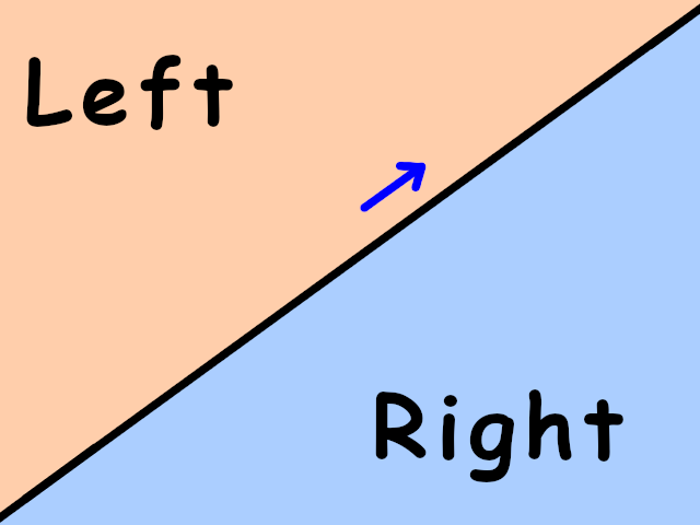
Blue arrow indicates forward direction.
Now, given a triangle \(V_0V_1V_2\) oriented counterclockwise, we can pick any of its edges, say, \(V_0V_1\) (in the same order as they go in the triangle!), and look at what's to the left of this edge. It turns out that in this setup the the triangle itself is always to the left of its edges:
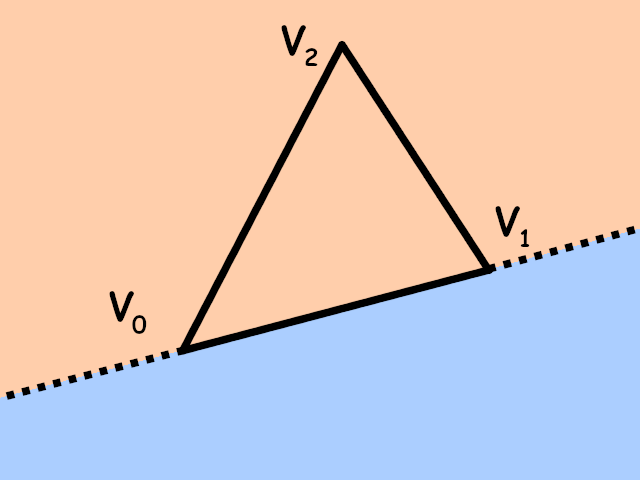
The same happens if we take edges \(V_1V_2\) or \(V_2V_0\): the triangle will be to the left of these edges. Note that if we take the edges in reverse orientation, namely \(V_1V_0\), \(V_2V_1\) and \(V_0V_2\), the triangle will be to the right of them.
Now, if you look closely at the image above, you'll see that the only points to the left of all three edges are precisely the points inside the triangle! So, here's an algorithm for detecting if a point is inside the triangle: simply check that the point is to the left of all three edges specified in counter-clockwise order!
How can we check if a point is to the left of an edge? Thankfully, that's exactly what a determinant can tell us. Specifically, the determinant composed of two vectors \(A\) and \(B\)
\[ \det(A,B) = \begin{vmatrix} A_x & B_x \\ A_y & B_y \end{vmatrix} \]is positive when the rotation from \(A\) to \(B\) is counterclockwise, and is negative otherwise. So, given a triangle \(V_0V_1V_2\) and any point \(P\), the point \(P\) is to the left of an edge \(V_0V_1\) precisely if the rotation from the vector \(V_1 - V_0\) to the vector \(P - V_0\) is counterclockwise:
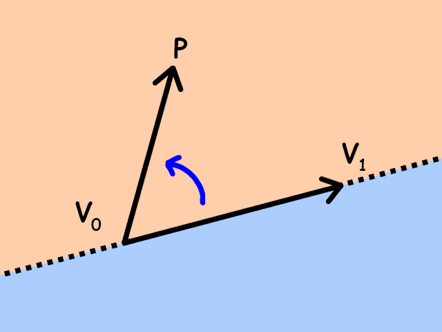
So, for the point \(P\) to be to the left of the edge \(V_0V_1\) we need the following determinant to be positive:
\[ det(V_1 - V_0, P - V_0) = \begin{vmatrix} V_{1x} - V_{0x} & P_x - V_{0x} \\ V_{1y} - V_{0y} & P_y - V_{0y} \end{vmatrix} > 0 \]Repeat this check for all three edges, and if all three determinants are positive, the point is inside a triangle!
Rasterizing a triangle: the code
Let's implement this algorithm. First, we'll need a few helper functions. Later all our computations will work with 4D vectors, as is customary in 3D graphics (to encode affine transformations and perspective projection as matrices), so lets make a function for converting a 3D point into a 4D vector in homogeneous coordinates:
namespace rasterizer
{

    ...

    inline vector4f as_vector(vector3f const & v)
    {
        return {v.x, v.y, v.z, 0.f};
    }

    inline vector4f as_point(vector3f const & v)
    {
        return {v.x, v.y, v.z, 1.f};
    }

}
I've also added a function for converting vectors to 4D homogeneous coordinates; we won't use it in this article, but it will be useful later.
Now, we also need a subtraction operator for our 4D vectors, and a function to compute a 2x2 determinant. Since we're working with 4D vectors, our function will look a bit strange: it will take two 4D vectors and compute the determinant of their X-Y parts (i.e. the determinant after projecting to the XY plane):
namespace rasterizer
{

    ...

    inline vector4f operator - (vector4f const & v0, vector4f const & v1)
    {
        return {v0.x - v1.x, v0.y - v1.y, v0.z - v1.z, v0.w - v1.w};
    }

    inline float det2D(vector4f const & v0, vector4f const & v1)
    {
        return v0.x * v1.y - v0.y * v1.x;
    }

}
I'm calling it det2D to specifically indicate that it is a 2D determinant in the XY plane.
Finally, since we're going to fill in specific pixels, let's add a convenience method to our image_view that picks a specific pixel:
struct image_view
{
    color4ub * pixels = nullptr;
    std::uint32_t width = 0;
    std::uint32_t height = 0;

    color4ub & at(std::uint32_t x, std::uint32_t y) const
    {
        return pixels[x + y * width];
    }
};
We're ready to finally implement triangle rasterization! Let's declare our new drawing function in renderer.hpp:
...

#include <rasterizer/draw_command.hpp>

namespace rasterizer
{

    ...

    void draw(image_view const & color_buffer, draw_command const & command);

}
And let's implement it in renderer.cpp. For each input triangle, we iterate over the screen pixels, test if they are contained in the triangle, and fill them:
...

void draw(image_view const & color_buffer, draw_command const & command)
{
    for (std::uint32_t vertex_index = 0;
        vertex_index + 2 < command.mesh.vertex_count;
        vertex_index += 3)
    {
        auto v0 = as_point(command.mesh.positions[vertex_index + 0]);
        auto v1 = as_point(command.mesh.positions[vertex_index + 1]);
        auto v2 = as_point(command.mesh.positions[vertex_index + 2]);

        for (std::int32_t y = 0; y < color_buffer.height; ++y)
        {
            for (std::int32_t x = 0; x < color_buffer.width; ++x)
            {
                vector4f p{x + 0.5f, y + 0.5f, 0.f, 0.f};

                float det01p = det2D(v1 - v0, p - v0);
                float det12p = det2D(v2 - v1, p - v1);
                float det20p = det2D(v0 - v2, p - v2);

                if (det01p >= 0.f && det12p >= 0.f && det20p >= 0.f)
                    color_buffer.at(x, y) = to_color4ub(command.mesh.color);
            }
        }
    }
}
And that's it! Since our triangles are defined as triples of vertices, we iterate with vertex_index += 3, and the condition vertex_index + 2 < vertex_count makes sure we don't overshoot the input vertex buffer even if the user supplied a vertex_count that is not a multiple of 3.
We could move the conversion to color4ub out of the loop, but we'll have to bring it back inside the loop in the next part of the tutorial anyway.
Now, to use this function, simply define some array of vertices in our main loop, and call the draw command after clearing the screen, like this:
...

clear(color_buffer, {0.8f, 0.9f, 1.f, 1.f});

vector3f vertices[] =
{
    {100.f, 100.f, 0.f},
    {200.f, 100.f, 0.f},
    {100.f, 200.f, 0.f},
};

draw(color_buffer,
    draw_command {
        .mesh = {
            .positions = vertices,
            .vertex_count = 3,
            .color = {1.f, 0.f, 0.f, 1.f},
        }
    }
);

...
And you should finally see a triangle on screen:
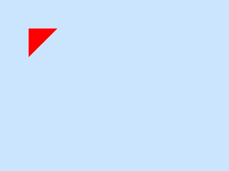
Our first triangle! It even took less code than in Vulkan.
Optimizing pixel traversal
At 1920x1080 resolution on my machine the whole frame currently takes about 6.5 ms to render. Recall that simply clearing the draw buffer and blitting the result to screen took about 3.7 ms, so we're spending something around 3 ms to draw a single triangle. We can draw about 4 triangles in total before we go below 60 FPS. That's not just slow, that's simply unacceptable.
Right now we're iterating over the whole color buffer to find pixels that are inside the triangle, even if the triangle itself is the size of 1 pixel. We can do much better: find the screen-space bounding box of the triangle (i.e. the min and max X and Y coordinates), and only traverse these pixels! Here's an image explaining that:
Blue area is the triangle bounding box in pixels.
So, let's rewrite the rasterization code:
std::int32_t xmin = std::min({std::floor(v0.x), std::floor(v1.x), std::floor(v2.x)});
std::int32_t xmax = std::max({std::floor(v0.x), std::floor(v1.x), std::floor(v2.x)});
std::int32_t ymin = std::min({std::floor(v0.y), std::floor(v1.y), std::floor(v2.y)});
std::int32_t ymax = std::max({std::floor(v0.y), std::floor(v1.y), std::floor(v2.y)});

for (std::int32_t y = ymin; y <= ymax; ++y)
{
    for (std::int32_t x = xmin; x <= xmax; ++x)
    {
        vector4f p{x + 0.5f, y + 0.5f, 0.f, 0.f};

        float det01p = det2D(v1 - v0, p - v0);
        float det12p = det2D(v2 - v1, p - v1);
        float det20p = det2D(v0 - v2, p - v2);

        if (det01p >= 0.f && det12p >= 0.f && det20p >= 0.f)
            color_buffer.at(x, y) = to_color4ub(command.mesh.color);
    }
}
Notice that the x < width changed to x <= xmax. We could probably use ceil instead of floor for xmax and ymax, and use x < xmax in this case. It doesn't really matter.
Though, with this code we might start drawing out of bounds of the screen, if the triangle is somewhere outside it. So, for a safety measure (i.e. to prevent crashes), let's constrain the bounding box to the visible area before iterating over it:
xmin = std::max<std::int32_t>(0, xmin);
xmax = std::min<std::int32_t>(color_buffer.width - 1, xmax);
ymin = std::max<std::int32_t>(0, ymin);
ymax = std::min<std::int32_t>(color_buffer.height - 1, ymax);
I'm explicitly specifying min<std::int32_t>(color_buffer.width - 1, xmax) instead of just min(color_buffer.width - 1, xmax) because otherwise the compiler wouldn't be able to pick the correct min function template specialization: the first argument is unsigned, and the second one is signed.
With this optimization in place, you should still see the same triangle on the screen, but now the frame takes something like 3.8 ms to render, meaning that the triangle itself takes something about 0.1 ms. That's a 30-fold increase in performance!
Notice that now the performance of rasterizing a triangle directly depends on its size. This is actually the case for GPUs, too! Try rendering a thousand full-screen rectangles with any graphics API and you'll notice that it's much slower than drawing a million tiny triangles.
Fixing triangle orientation
You might have noticed that I've tricked you a little bit. The triangle that we're currently drawing with \(V_0=(100,100)\), \(V_1=(200,100)\), \(V_2=(100,200)\) is oriented clockwise on the screen, not counterclockwise! Our rasterization algorithm shouldn't work!
The trick is that the determinant formulas work only in the usual maths coordinate system, where X goes to the right and Y goes up, meaning that the rotation from X to Y is a counterclockwise rotation. But in screen coordinates Y goes down, from top to bottom of the screen (or window), while X still goes to the right, and in screen space the rotation from X to Y is a clockwise rotation!
This messes up everything related to orientation, but in a controllable way: clockwise and counterclockwise simple swap places. The triangle we're rasterizing right now goes clockwise when seen on the screen, but it would be counterclockwise if it existed in the usual maths XY plane with the same coordinates!
Though, this still means that if we change the orientation of our triangle, it simply wouldn't be drawn. Swap any two vertices in it and it disappears:
vector3f vertices[] =
{
    {100.f, 100.f, 0.f},
    {100.f, 200.f, 0.f}, // I swapped
    {200.f, 100.f, 0.f}, // these two
};
This is probably not what we want, right? It wouldn't be a particularly nice API to use if we had to constantly think about triangle orientations when drawing simple 2D stuff. Let's fix that.
What we need to do is detect if the triangle is counterclockwise on screen, i.e. clockwise if Y went up and not down. But that's exactly what the determinant tells us: it is less than zero when the triangle is clockwise in math XY coordinates:
\[ \det(V_1-V_0,V_2-V_0) = \begin{vmatrix} V_{1x}-V_{0x} & V_{2x}-V_{0x} \\ V_{1y}-V_{0y} & V_{2y}-V_{0y} \end{vmatrix} < 0 \]If that happens, we need to patch the orientation so that our rasterization algorithm works. This can be achieved, again, by swapping any two vertices of the input triangle:
auto v0 = as_point(command.mesh.positions[vertex_index + 0]);
auto v1 = as_point(command.mesh.positions[vertex_index + 1]);
auto v2 = as_point(command.mesh.positions[vertex_index + 2]);

float det012 = det2D(v1 - v0, v2 - v0);

// Is it counterclockwise on screen?
bool const ccw = det012 < 0.f;

if (ccw)
{
    std::swap(v1, v2);
    det012 = -det012;
}
And with this fix, the triangle with messed up orientation should still appear on screen.
By the way, that's a ton of determinants, wouldn't it affect performance? Well, yes it would, but we'll actually need all these determinants in the next part, when we start interpolating vertex attributes inside the triangle. This is also why I'm precautiously fixing the det012 sign when swapping the vertices.
Back-face culling
Now is a good time to make a small diversion and implement something that is only useful for actual 3D graphics (which we'll tackle in part 4), but it is very relevant to what we did in the previous section with triangle orientations.
I'm talking about back-face culling, of course! There's this neat fact from 3D geometry: if we're rendering a nice 3D mesh without holes or single triangles sticking out (technically, a manifold mesh), and we stick to the convention that all the triangles are oriented counterclockwise when looking at the mesh from the outside, then we can completely skip rendering triangles that appear clockwise on screen! This happens because these triangle will be at the back of the mesh, and their pixels will be replaced by the front-facing triangles anyway. Here's a picture:
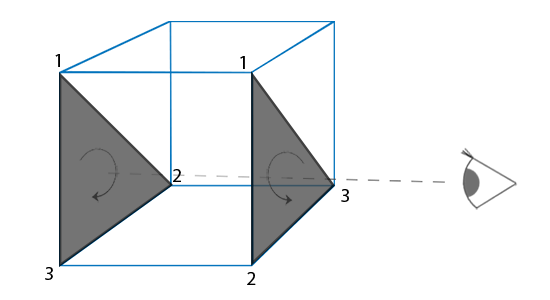
This usually lets us skip drawing half of all the triangles of a 3D mesh. This is huge for our poor CPU rasterizer, which already struggles with just a few triangles!
Luckily, we already know how to check if the triangle is oriented clockwise or counterclockwise. Though, we probably don't want to do back-face culling by default! So, let's create a new file with various settings for our rendering pipeline:
#pragma once

namespace rasterizer
{

    enum class cull_mode
    {
        none,
        cw,
        ccw,
    };

}
Here e.g. cull_mode::cw will cull (i.e. not draw) clockwise triangles, which is the standard setting for 3D manifold meshes. Now add this setting to our draw command, with culling turned off by default:
struct draw_command
{
    struct mesh mesh;
    enum cull_mode cull_mode = cull_mode::none;
};
And finally let's support this setting in the rasterization code. We have three cases:
- For
cull_mode::nonewe don't cull any triangles - For
cull_mode::cwwe cull clockwise triangles, i.e. those withccw == false - For
cull_mode::ccwwe cull counterclockwise triangles, i.e. those withccw == true
That should be easy:
// Is it counterclockwise on screen?
bool const ccw = det012 < 0.f;

switch (command.cull_mode)
{
case cull_mode::none:
    break;
case cull_mode::cw:
    if (!ccw)
        continue; // move to the next triangle
    break;
case cull_mode::ccw:
    if (ccw)
        continue; // move to the next triangle
    break;
}

if (ccw)
{
    std::swap(v1, v2);
    det012 = -det012;
}
And that's it, just a single switch-case! As I've said, this will be handy later, when we work on 3D stuff.
Edge rasterization rules
There's one thing I've completely glossed over, but that is an important part of any decent production-ready rasterizer. If we draw two triangles that share an edge, what will happen with the pixels on the shared edge? Ideally any pixel center should fall into only one of the triangles, unless it sits precisely on the edge, in which case it will be drawn twice (once for each triangle). Though, due to numerical precision, it can happen for other pixels, too, or some pixels might actually not fall into any of the two triangles and completely disappear. This is a problem:
- Disappearing pixels mean that we will have pixel-sized holes in our meshes
- Overlapping pixels mean that when rendering semi-transparent stuff, these overlapping pixels will be drawn twice and will have a wrong color
This is why any decent graphics API provides us with the guarantee that there will be no overlapping or disappearing pixels in this case, ever.
The usual way to fix this uses two tricks:
- Use special rules designed to consistently draw (or not draw) certain triangle edges to prevent overlapping
- Use integer or fixed-point math to get rid of floating-point inconsistencies
See, for example, this amazing article series on writing a rasterizer by Kristoffer Dyrkorn, which explains how all this works.
From my tests, though, when rendering 3D scenes with various transformations and projection matrices, this problem basically never manifests itself. It's just incredibly rare for a random edge to cause disappearing or overlapping pixels. So, I just completely ignore this problem in my rasterizer! I do feel a bit bad about it, though.
Matrix transformations
Finally, let's stress-test our rasterizer by drawing our triangles many times in different places! Wait, does it mean that we need to fill a whole array of vertices with all the coordinates of all the copies of our triangle? That's a bummer.
The usual solution to this is to have a special per-object transformation that can be applied to object's vertices. This way we can have a single immutable array of vertex positions, and we can move the object around or even draw copies of the object without changing the vertices!
Usually we restrict ourselves to affine transformations, i.e. rotations, scalings, translations, shears, that sort of thing, because they can be nicely and efficiently implemented using 4x4 matrices in homogeneous coordinates. For example, a matrix of translating by a vector \((X, Y)\) will look like
\[ \begin{pmatrix}1&0&0&X\\0&1&0&Y\\0&0&1&0\\0&0&0&1\end{pmatrix} \]This might be an overkill for something as simple as moving by a 2D vector, but the code we'll write right now will work verbatim also for rotations, scalings, and even for crazy 3D transformations!
So, let's add a matrix class to our types.hpp file, and implement matrix-vector multiplication:
struct matrix4x4f
{
    float values[16];

    static matrix4x4f identity()
    {
        return matrix4x4f{
            1.f, 0.f, 0.f, 0.f,
            0.f, 1.f, 0.f, 0.f,
            0.f, 0.f, 1.f, 0.f,
            0.f, 0.f, 0.f, 1.f,
        };
    }
};

inline vector4f operator * (matrix4x4f const & m, vector4f const & v)
{
    vector4f result{0.f, 0.f, 0.f, 0.f};

    result.x = m.values[ 0] * v.x + m.values[ 1] * v.y + m.values[ 2] * v.z + m.values[ 3] * v.w;
    result.y = m.values[ 4] * v.x + m.values[ 5] * v.y + m.values[ 6] * v.z + m.values[ 7] * v.w;
    result.z = m.values[ 8] * v.x + m.values[ 9] * v.y + m.values[10] * v.z + m.values[11] * v.w;
    result.w = m.values[12] * v.x + m.values[13] * v.y + m.values[14] * v.z + m.values[15] * v.w;

    return result;
}
Yeah, I should've written a loop, but we don't have an operator for indexing a vector, so whatever.
Add this transformation matrix to our draw command, which will be an identity transform (i.e. no transformation) by default:
struct draw_command
{
    struct mesh mesh;
    enum cull_mode cull_mode = cull_mode::none;
    matrix4x4f transform = matrix4x4f::identity();
};
And apply this matrix in our rasterization code, immediately when we read the input vertices:
auto v0 = command.transform * as_point(command.mesh.positions[vertex_index + 0]);
auto v1 = command.transform * as_point(command.mesh.positions[vertex_index + 1]);
auto v2 = command.transform * as_point(command.mesh.positions[vertex_index + 2]);
Now, let's draw a 10x10 table of triangles with different colors, using a single array of 3 vertices, and also move them with the mouse:
clear(color_buffer, {0.8f, 0.9f, 1.f, 1.f});

vector3f positions[] =
{
    {  0.f,   0.f, 0.f},
    {100.f,   0.f, 0.f},
    {  0.f, 100.f, 0.f},
};

for (int i = 0; i < 100; ++i)
draw(color_buffer,
    draw_command{
        .mesh = {
            .positions = positions,
            .vertex_count = 3,
            .color = {(i % 3) == 0, (i % 3) == 1, (i % 3) == 2, 1.f},
        },
        .transform = {
            1.f, 0.f, 0.f, mouse_x + 100.f * (i % 10),
            0.f, 1.f, 0.f, mouse_y + 100.f * (i / 10),
            0.f, 0.f, 1.f, 0.f,
            0.f, 0.f, 0.f, 1.f,
        },
    }
);
We should get something like this:
Not bad, huh? Next time we'll try to draw gradients on triangles instead of a fixed color.
| \(\leftarrow\) Part 1: Clearing the screen | Source code for this part | Part 3: Interpolating colors \(\rightarrow\) |