The code for this part is available in this commit.
So, now we can draw some triangles and even put color gradients on them, but they're all rather flat. We want to go full 3D!
Complete 3D support will take several steps (tutorial parts 4-6), but first let's change our coordinate system to something more convenient and conventional.
Contents
Viewport
All graphics APIs have the concept of a viewport: a rectangular area on the screen/window/offscreen texture/etc, where rendering currently takes place. Nothing will be rendered outside the viewport, ever.
It might sound a bit silly — for example, why doesn't the viewport coincide with the full screen? Well, sometimes you want to specifically render to only part of the screen. Maybe you're rendering 4 different projections of some CAD model, or maybe you're generating mipmaps for a particular region in a texture atlas. This viewport setting is rarely needed, but it is sometimes immensely useful.
Another useful thing is to get rid of the window coordinate system in pixels, and use some virtual coordinates that don't depend on the screen. The typical solution in graphics APIs is to say that X and Y coordinates are in the range \([-1,1]\), with Y going up (and not down, like in pixel coordinate system). This coordinate space is called normalized device coordinates, or NDC (normalized here means that the coordinates are in a fixed \([-1,1]\) range, and don't depend on screen size). Of course, we'll have to do the conversion to actual pixels somewhere before rasterizing a triangle.
So, let's create a new file for the viewport and define it, together with a helpful function for converting from \([-1,1]\) to pixels:
#pragma once

#include <rasterizer/vector.hpp>

#include <cstdint>

namespace rasterizer
{

    struct viewport
    {
        std::int32_t xmin, ymin, xmax, ymax;
    };

    inline vector4f apply(viewport const & viewport, vector4f v)
    {
        v.x = viewport.xmin + (viewport.xmax - viewport.xmin) * (0.5f + 0.5f * v.x);
        v.y = viewport.ymin + (viewport.ymax - viewport.ymin) * (0.5f - 0.5f * v.y);
        return v;
    }

}
Here, xmax and ymax are exclusive, i.e. the right-most pixel included in the viewport will have the X coordinate of xmax-1.
Now, let's add this viewport to our draw function as a parameter:
...

#include <rasterizer/viewport.hpp>

...

    void draw(image_view const & color_buffer, viewport const & viewport,
        draw_command const & command);

...
I'm not adding it to the draw_command struct, because it's kind of a property of the output buffer and not of the rendered objects themselves. We could probably create a render_target class containing a color buffer and a viewport, like this:
struct render_target
{
    image_view color_buffer;
    viewport viewport;
};
and use it as a parameter to the draw function, but I didn't bother doing this.
Now, we need to implement viewport support in our rasterization code. This is rather straightforward: just convert the coordinates from \([-1,1]\) to screen pixels using the apply function we made earlier, and make sure we never touch pixels outside the viewport:
...

void draw(image_view const & color_buffer, viewport const & viewport,
    draw_command const & command)
{
    ...


    auto v0 = command.transform * as_point(command.mesh.positions[vertex_index + 0]);
    auto v1 = command.transform * as_point(command.mesh.positions[vertex_index + 1]);
    auto v2 = command.transform * as_point(command.mesh.positions[vertex_index + 2]);

    v0 = apply(viewport, v0);
    v1 = apply(viewport, v1);
    v2 = apply(viewport, v2);

    ...

    std::int32_t xmin = std::max<std::int32_t>(viewport.xmin, 0);
    std::int32_t xmax = std::min<std::int32_t>(viewport.xmax, color_buffer.width) - 1;
    std::int32_t ymin = std::max<std::int32_t>(viewport.ymin, 0);
    std::int32_t ymax = std::min<std::int32_t>(viewport.ymax, color_buffer.height) - 1;

    xmin = std::max<float>(xmin, std::min({std::floor(v0.x), std::floor(v1.x), std::floor(v2.x)}));
    xmax = std::min<float>(xmax, std::max({std::floor(v0.x), std::floor(v1.x), std::floor(v2.x)}));
    ymin = std::max<float>(ymin, std::min({std::floor(v0.y), std::floor(v1.y), std::floor(v2.y)}));
    ymax = std::min<float>(ymax, std::max({std::floor(v0.y), std::floor(v1.y), std::floor(v2.y)}));

    ...
}
Notice that I'm also doing stuff like max(viewport.xmin, 0) in case somebody gives us a viewport that is larger than the screen itself.
Now we need to update our main rendering loop to use the viewport. Let's just draw a single triangle for a quick test:
...

viewport viewport
{
    .xmin = 0,
    .ymin = 0,
    .xmax = (std::int32_t)color_buffer.width,
    .ymax = (std::int32_t)color_buffer.height,
};

clear(color_buffer, {0.9f, 0.9f, 0.9f, 1.f});

vector3f positions[]
{
    { 0.f,   0.5f, 0.f},
    {-0.5f, -0.5f, 0.f},
    { 0.5f, -0.5f, 0.f},
};

vector4f colors[]
{
    {1.f, 0.f, 0.f},
    {0.f, 1.f, 0.f},
    {0.f, 0.f, 1.f},
};

draw(color_buffer, viewport,
    draw_command {
        .mesh = {
            .positions = {positions},
            .colors = {colors},
            .count = 3,
        },
    }
);

...
We should get a colored triangle around the center of the screen:
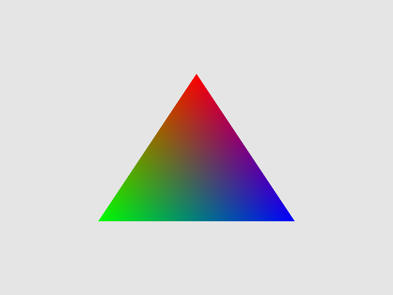
Note that if we change the size of our window, the triangle will scale alongside it, because now it exists in a virtual relative coordinate system. In particular, the triangle can get flattened along one axis without changing along the other axis (if we do the same with the window). This is a feature, not a bug: using a simple coordinate system like \([-1,1]\) will help us simplify the formulas later.
Indexed rendering
It's time we moved on from triangles to something more substantial. When describing 3D meshes, it often happens that the same vertex is shared among many triangles (in fact, among 6 triangles on average, as a consequence of Euler's formula). Our current API doesn't allow that: we'd have to duplicate the vertex for each triangle containing it.
Instead, graphics APIs usually support indexed rendering: the triangles don't contain vertices, but instead refer to them by indices. So, we have a separate array of vertices which come in any order, and an array of triangles, where each triangle is a triple of vertex indices. This allows us to remove vertex duplication: the only thing that is duplicated is the index, which is always small (typically 2-4 bytes).
So, let's update our mesh definition to include indices:
...

struct mesh
{
    attribute<vector3f> positions = {};
    attribute<vector4f> colors = {};
    std::uint32_t const * indices = nullptr;
    std::uint32_t count = 0;
};

...
Note that I've renamed the vertex_count field to just count. If indices is non-null, we will use indexed rendering, and count specifies the number of indices in our index array (i.e the number of triangles times 3). If indices is null, we use the old version of non-indexed rendering, and count is the number of vertices.
Now, supporting indexed rendering in our rasterizer is very easy — just replace vertex_index + 0 with the actual vertex index in case we're using indexed rendering:
...

std::uint32_t i0 = vertex_index + 0;
std::uint32_t i1 = vertex_index + 1;
std::uint32_t i2 = vertex_index + 2;

if (command.mesh.indices)
{
    i0 = command.mesh.indices[i0];
    i1 = command.mesh.indices[i1];
    i2 = command.mesh.indices[i2];
}

auto v0 = command.transform * as_point(command.mesh.positions[i0]);
auto v1 = command.transform * as_point(command.mesh.positions[i1]);
auto v2 = command.transform * as_point(command.mesh.positions[i2]);

v0 = apply(viewport, v0);
v1 = apply(viewport, v1);
v2 = apply(viewport, v2);

auto c0 = command.mesh.colors[i0];
auto c1 = command.mesh.colors[i1];
auto c2 = command.mesh.colors[i2];

...
To test indexed rendering, replace our triangle with a square, so that we have 4 vertices and 2 triangles (thus 6 indices):
...

vector3f positions[]
{
    {-0.5f, -0.5f, 0.f},
    {-0.5f,  0.5f, 0.f},
    { 0.5f, -0.5f, 0.f},
    { 0.5f,  0.5f, 0.f},
};

vector4f colors[]
{
    {1.f, 0.f, 0.f},
    {0.f, 1.f, 0.f},
    {0.f, 0.f, 1.f},
    {1.f, 1.f, 1.f},
};

std::uint32_t indices[]
{
    0, 1, 2,
    2, 1, 3,
};

draw(color_buffer, viewport,
    draw_command{
        .mesh = {
            .positions = {positions},
            .colors = {colors},
            .indices = indices,
            .count = 6,
        },
    }
);

...
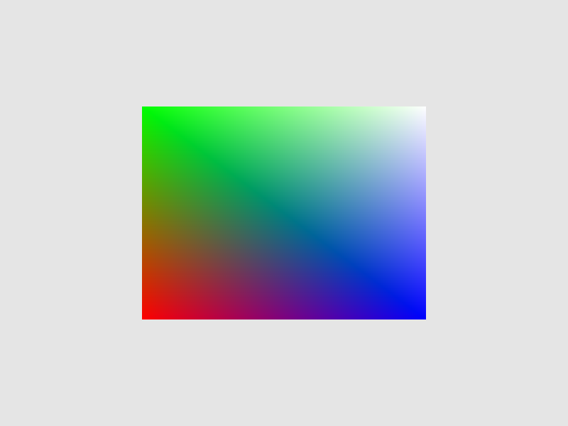
And we should get a nice rectangle:
3D transformations
I've promised you some 3D, but all we've done now is still 2D. Let's actually get to 3D!
You'd think that the 3rd coordinate of our vertices has something to do with 3D, but we're not using it yet: it is just completely ignored by our rasterizer. However, it is not ignored by our \(4\times 4\) transformation matrices!
Since our types.hpp file got really big, I've split it into vector.hpp, color.hpp and matrix.hpp. Since we'll be using a lot of various 3D matrix transformations later, I've added a bunch of utility functions for creating these transformations:
...

struct matrix4x4f
{
    float values[16];

    static matrix4x4f identity();
    static matrix4x4f scale(vector3f const & s);
    static matrix4x4f scale(float s);
    static matrix4x4f translate(vector3f const & s);
    static matrix4x4f rotateXY(float angle);
    static matrix4x4f rotateYZ(float angle);
    static matrix4x4f rotateZX(float angle);
};

...
with the usual implementations, as well as a very straightforward function for multiplying \(4\times 4\) matrices:
...

inline matrix4x4f operator * (matrix4x4f const & m1, matrix4x4f const & m2)
{
    matrix4x4f result
    {
        0.f, 0.f, 0.f, 0.f,
        0.f, 0.f, 0.f, 0.f,
        0.f, 0.f, 0.f, 0.f,
        0.f, 0.f, 0.f, 0.f,
    };

    for (int i = 0; i < 4; ++i)
        for (int j = 0; j < 4; ++j)
            for (int k = 0; k < 4; ++k)
                result.values[4 * i + j] += m1.values[4 * i + k] * m2.values[4 * k + j];

    return result;
}

...
Why did I keep all these functions in the header, instead of creating a separate matrix.cpp file? I don't know. Probably out of pure laziness.
Now, let's rotate our poor square around the Y axis:
...

int main()
{
    ...

    float time = 0.f;

    ...

    while (running)
    {
        ...

        time += dt;

        ...

        matrix4x4f transform = matrix4x4f::rotateZX(time);

        draw(color_buffer, viewport,
            draw_command{
                .mesh = {
                    .positions = {positions},
                    .colors = {colors},
                    .indices = indices,
                    .count = 6,
                },
                .transform = transform,
            }
        );

        ...
    }
}
Is it what you expected? Well, it's quite heavily distorted along the X axis due to the aspect ratio of the window, but otherwise that' how a rotating rectangle would look like if you looked at it from far away. Or would it? It's hard to say when our mesh is still in 2D.
The Cube
Instead of dull, flat 2D objects, let's use something that actually uses the 3 dimensions. Something canonical and well-known. Something like a cube!
A cube has 8 vertices, but I want each face of the cube to have its own color, so I can't share vertices between different faces. So, I'll have 4 square faces, each composed of 4 vertices and 2 triangles. Setting up the cube mesh is rather boring, so I moved it to a separate pair of header and source files. The header file simply exposes the cube as a ready-to-use mesh:
#pragma once

#include <rasterizer/mesh.hpp>

namespace rasterizer
{

    extern const mesh cube;

}
Now we can use this mesh in place of our square in the main rendering loop:
...

#include <rasterizer/cube.hpp>

...

        draw(color_buffer, viewport,
            draw_command{
                .mesh = cube,
                .transform = transform,
            }
        );

...
Huh?...
Well, our cube occupies the region \([-1,1]^3\) of the 3D space, which is the same as the region occupied by the screen in virtual XY coordinates. That's why the cube fills the whole screen.
Let's scale it down by a factor of 2 first:
...

matrix4x4f transform = matrix4x4f::scale(0.5f) * matrix4x4f::rotateZX(time);

...
Now, let's remove the distortion due to screen aspect ratio, by scaling the X coordinate in proportion to the aspect ratio:
...

matrix4x4f transform = matrix4x4f::scale({height * 1.f / width, 1.f, 1.f})
    * matrix4x4f::scale(0.5f) * matrix4x4f::rotateZX(time);

...
It's still weird. Let's rotate it along some other axis as well, using a different rotation speed:
...

matrix4x4f transform = matrix4x4f::scale({height * 1.f / width, 1.f, 1.f})
    * matrix4x4f::scale(0.5f)
    * matrix4x4f::rotateZX(time)
    * matrix4x4f::rotateXY(time * 1.61f);

...
That's definitely a cube, but the drawing order of the faces is wrong: some faces that should be at the back are drawn on top of faces that should've been at front!
This makes sense: after all, we didn't do literally anything to prevent this from happening. The full solution to this problem will come in part 6 of this tutorial; for now, we can simply use the fact that a cube is a convex polyhedron, and back-face culling should fix the issue for now:
...

draw(color_buffer, viewport,
    draw_command{
        .mesh = cube,
        .cull_mode = cull_mode::cw,
        .transform = transform,
    }
);

...
Now that's a perfectly good cube! It's definitely 3D, and it's even rotating.
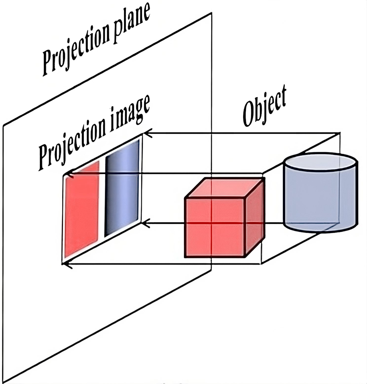
Though, it still looks a little bit flat, as if we were looking at it from a large distance through a spyglass or a telescope. This is because we're using an orthographic projection: a type of 3D-to-2D projection that maps the image parallel to some direction vector. In our case, this direction is the Z axis: the rasterizer simply ignores it, and takes the remaining XY coordinates to project the point to the screen:
Perspective projection: theory
The issue with orthographic projection is that it doesn't give us any information about how far certain objects are in relation to each other, as if they are all infinitely far. This is not how eyes and camera lenses work: they clearly let us distinguish nearby and far away objects, simply because the latter appear smaller. This is a feature of perspective projection — it makes distanct objects smaller:
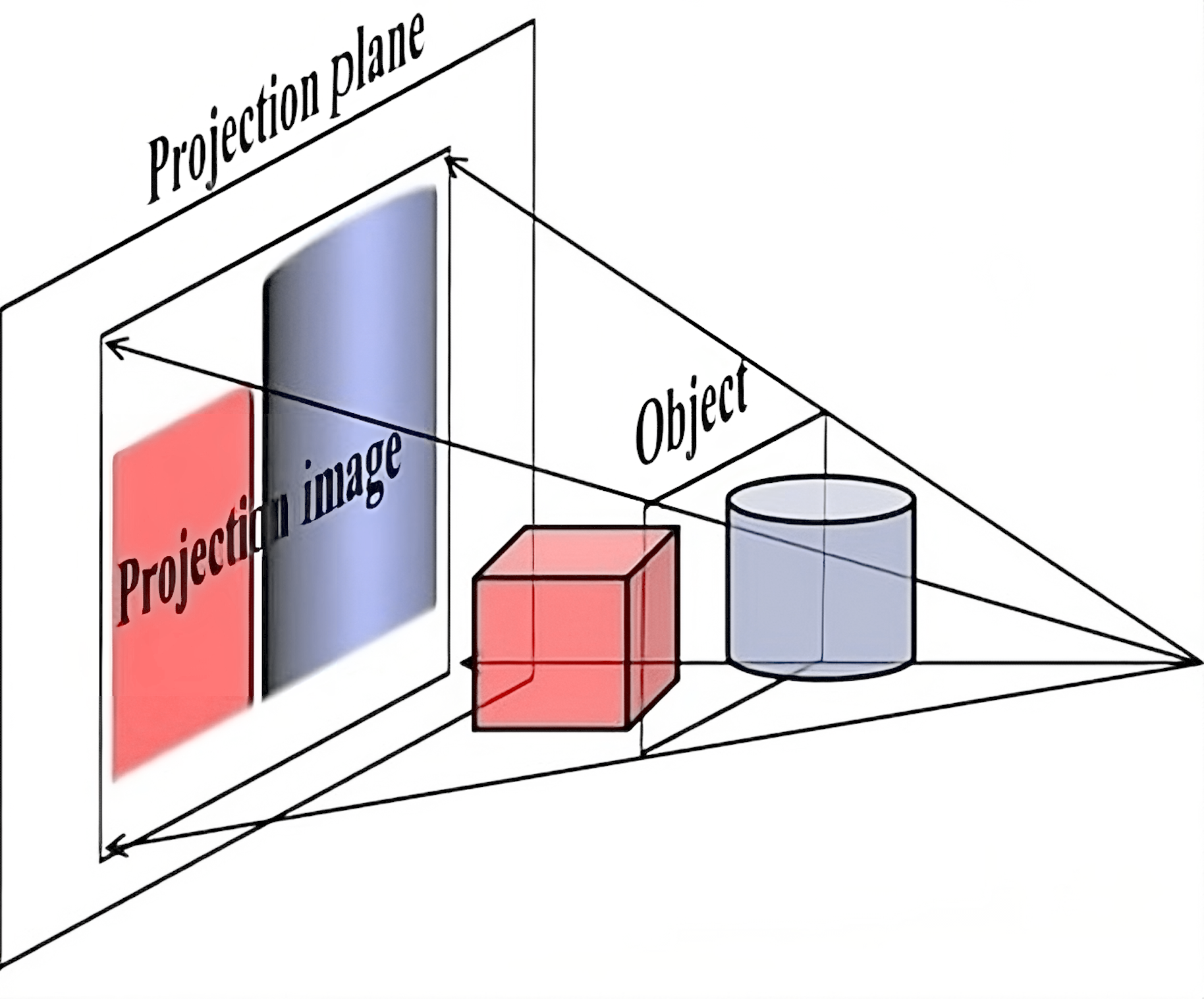
It achieves this simply by dividing the XY coordinates by the Z coordinate before projecting to the screen. This way, further objects will appear smaller on screen.
However, dividing by a coordinate is a non-linear operation, meaning that it cannot be done using a matrix. We'll have to support dividing by Z in our rasterizer explicitly.
But what if we don't want to divide? What if an orthographic projection is exactly what we need, e.g. for an isometric perspective in an RPG game? We need some way to switch between perspective and orthographic modes.
Luckily, our ancestors already figured this out: use the W coordinate! Specifically, set \(W=1\) if you want orthographic projection, or set \(W=Z\) if you want the perspective one. This way, our rasterizer can always divide by \(W\): for an orthographic projection this will be a no-op. This step is called the perspective divide.
Conveniently, leaving \(W=1\) or setting \(W=Z\) can also be done using a matrix, the so-called projection matrix. After applying this matrix, our points are in a 4D space called the clip space (the name will make more sense in the next part). Applying perspective division in clip space results in points in NDC. Note that points in clip space can have \(W\neq 1\) now, due to the perspective projection matrix.
Though, usually the full formula is a bit more complicated. Firstly, we usually take \(-Z\) as our "forward" direction in 3D, just so that XYZ would form a right-handed coordinate system (which affects stuff like triangle orientations, normal vector directions, etc).
Secondly, the Z coordinate is also divided by W, which in case of a perspective projection would simply give \(\frac{Z}{Z} = 1\). However, we want to use this value later for the depth buffer, and we want to constrain it to be in some predefined range because the depth buffer precision is limited. This range is usually \([-1,1]\) in OpenGL or \([0,1]\) in other graphics APIs. We'll stick to the OpenGL convention here.
To limit the Z coordinate after dividing by W, we choose two distances called near and far that will become \(-1\) and \(1\) respectively after applying our projection matrix and doing the perspective divide. They effectively define the range of distances that our camera can see:
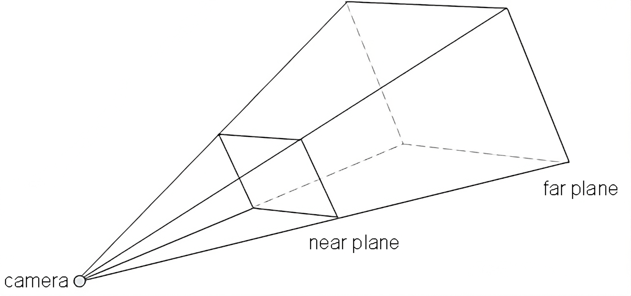
A matrix can only replace a coordinate \(Z\) with a linear combination of other coordinates, and we probably don't want to involve X or Y here, so the formula for the clip-space\(Z\) coordinate after applying our matrix should be something like \(A\cdot Z + B\cdot W\). Meanwhile, for the clip-space \(W\) coordinate, the matrix should simply set \(W=-Z\). Here's the current look of our perspective projection matrix:
\[ \begin{pmatrix} 1 & 0 & 0 & 0 \\ 0 & 1 & 0 & 0 \\ 0 & 0 & A & B \\ 0 & 0 & -1 & 0 \end{pmatrix} \](We're not doing anything with X and Y for now).
Recall that for input vertices (in world space, before applying the projection matrix) we have \(W=1\) (because they are points in homogeneous coordinates). We want \(Z=-\text{near}\) to become \(-1\) after applying the matrix and perspective divide, and similarly for \(Z=-\text{far}\) and \(1\). This leads to a system of equations
\[ \frac{A\cdot (-\text{near}) + B}{\text{near}} = -1 \\ \frac{A\cdot (-\text{far}) + B}{\text{far}} = 1 \\ \]Solving this, we get
\[ A = -\frac{\text{far}+\text{near}}{\text{far}-\text{near}} \\ B = -\frac{2\cdot\text{far}\cdot\text{near}}{\text{far}-\text{near}} \]and the matrix looks like
\[ \begin{pmatrix} 1 & 0 & 0 & 0 \\ 0 & 1 & 0 & 0 \\ 0 & 0 & -\frac{\text{far}+\text{near}}{\text{far}-\text{near}} & -\frac{2\cdot\text{far}\cdot\text{near}}{\text{far}-\text{near}} \\ 0 & 0 & -1 & 0 \end{pmatrix} \]Though, if we use this matrix, things will look weird, because our X and Y coordinate ranges also depend on Z now (since the rendering engine will divide by Z in case of perspective projection). I'll skip the full derivation (see here), but the final matrix turns out to be
\[ \begin{pmatrix} \frac{1}{\tan\frac{\text{fovX}}{2}} & 0 & 0 & 0 \\ 0 & \frac{1}{\tan\frac{\text{fovY}}{2}} & 0 & 0 \\ 0 & 0 & -\frac{\text{far}+\text{near}}{\text{far}-\text{near}} & -\frac{2\cdot\text{far}\cdot\text{near}}{\text{far}-\text{near}} \\ 0 & 0 & -1 & 0 \end{pmatrix} \]where \(\text{fovX}\) is the field of view angle for the X direction (i.e. how much does the camera see horizontally), and \(\text{fovY}\) is a similar angle for Y.
Perspective projection: implementation
A lot of formulas again! Jeez, who knew that 3D rendering is just a ton of math and almost nothing else...
Anyway, let's finally implement perspective projection. This will take a tiny amount of code! First, let's add a perspective division helper function in vector.hpp:
...

inline vector4f perspective_divide(vector4f v)
{
    v.x /= v.w;
    v.y /= v.w;
    v.z /= v.w;
    return v;
}

...
Now, apply it in our rasterizer right after reading vertex positions, before converting them to screen-space pixel coordinates:
...

auto v0 = command.transform * as_point(command.mesh.positions[i0]);
auto v1 = command.transform * as_point(command.mesh.positions[i1]);
auto v2 = command.transform * as_point(command.mesh.positions[i2]);

v0 = perspective_divide(v0);
v2 = perspective_divide(v1);
v1 = perspective_divide(v2);

v0 = apply(viewport, v0);
v1 = apply(viewport, v1);
v2 = apply(viewport, v2);

...
Nothing should change now, because we're still using an orthographic projection, and perspective divide is just dividing by \(1\). Let's add a helper function to matrix.hpp that implements a perspective projection matrix:
...

static matrix4x4f perspective(float near, float far, float fovY, float aspect_ratio)
{
    float top = near * std::tan(fovY / 2.f);
    float right = top * aspect_ratio;

    return matrix4x4f
    {
        near / right, 0.f, 0.f, 0.f,
        0.f, near / top, 0.f, 0.f,
        0.f, 0.f, -(far + near) / (far - near), - 2.f * far * near / (far - near),
        0.f, 0.f, -1.f, 0.f,
    };
}

...
Notice that I'm using aspect_ratio instead of fovX directly, so that it's easier to make a projection matrix that compensates the distortion created by the output window dimensions.
Now, set our transform matrix in the main rendering loop to apply a perspective projection after other transformations (except the scalings, we don't need them anymore):
...

matrix4x4f transform =
    matrix4x4f::perspective(0.01f, 10.f, M_PI / 3.f, width * 1.f / height)
    * matrix4x4f::rotateZX(time)
    * matrix4x4f::rotateXY(time * 1.61f);

...
Huh???
What we see is a rotating cube, but we're looking at it from inside the cube, at it's clearly wrong: there shouldn't be any weird intersecting triangles or crosses there.
We'll fix this in the next part; for now, let's simply move the cube away from the camera after rotating it, but before the projection matrix. The camera looks in the \(-Z\) direction, so that's the direction we need to move the cube along:
...

matrix4x4f transform =
    matrix4x4f::perspective(0.01f, 10.f, M_PI / 3.f, width * 1.f / height)
    * matrix4x4f::translate({0.f, 0.f, -5.f})
    * matrix4x4f::rotateZX(time)
    * matrix4x4f::rotateXY(time * 1.61f);

...
Finally, we get a truly 3D rotating cube with a perspective projection!
There are still a ton of issues with our code, which we'll be fixing in the next two parts.
| \(\leftarrow\) Part 3: Interpolating colors | Source code for this part | Part 5: Fixing issues with 3D \(\rightarrow\) |