The code for this part is available in this commit.
Last time, we got a nice rotating cube:
However, if we move the camera inside the cube, it looks horribly wrong:
What's going on?
Contents
Clipping
Recall that we've defined a range \([\text{near}, \text{far}]\) of Z-coordinates that our camera can see. What happens to the points outside of this range? Well, currently nothing happens, but given that we want to use the Z coordinate (after perspective divide) for the depth buffer, we don't have any reasonable way to deal with values outside this range.
The usual way to deal with them is to simply cut them off: nothing closer than \(\text{near}\) or further than \(\text{far}\) from the camera won't be drawn at all. However, a specific triangle can have a part that is inside the allowed Z-range, and another part that is outside it. This means that we'll need to literally cut off the outside part of the triangle, and only rasterize what's left. That's why we're calling the planes \(Z=-\text{near}\) and \(Z=-\text{far}\) the near and far clipping planes, or clip planes. Also, this is why the coordinate space after applying the projection matrix is called the clip space — as we'll see, this is precisely the space where this clipping happens.
Actually, there is another option to deal with the outside parts, called depth clamping: we simply clamp the post-perspective-divide Z value to the \([-1,1]\) range, and proceed. Though, this still requires us to do clipping by the \(W<0\) equation, as discussed below.
This doesn't explain the issue on the video above, though: we've set the near clipping plane to 0.01, which is clearly much closer than the cube.
What's going on is we're seeing objects behind the camera! When the camera is at the center of the cube, half of the cube is always behind it, and we're doing nothing to prevent these triangles from rasterizing. There's little sense in rendering what's behind the camera with a perspective projection, so we probably need to clip it as well.
Recall that after applying the projection matrix, the \(W\) coordinate contains the distance to the camera. It is positive if the point is in front of the camera, and it is negative if it is behind the camera. So, it seems that we need to cut off triangle parts with \(W \leq 0\) as well!
By the way, strictly speaking, we don't have to do clipping specifically. We could do the usual rasterization, and then check the properly interpolated Z and W coordinates. However, rasterization is costly, since it iterates a ton of pixels, while clipping is cheap — it's just a dozen floating-point operations.
I'm also not sure if rasterization would work correctly for triangles intersecting the \(W=0\) plane, but clipping definitely removes this case!
Clipping equations
Let's write down the exact equations that should be satisfied by points that survive clipping.
First, we've already decided that \(W > 0\) should rule out everything behind the camera.
Then, we want the Z values after perspective projection to be in the range \([-1, 1]\). If \((Z,W)\) are the coordinates of a point after applying the projection matrix, then perspective divide gives us \(\frac{Z}{W}\), and we want
\[ -1 < \frac{Z}{W} < 1 \]Knowing that \(W > 0\), we can rewrite this as
\[ -W < Z < W \]Now, here's a little trick: when written in this form, it actually implies that \(-W < W\), which can only happen if \(W > 0\)! So, if we take this equation, we don't need \(W > 0\) explicitly, since it is now implied.
Thus, we have just two equations:
\[ -W < Z \\ Z < W \]which we'll rewrite in a slightly more convenient form:
\[ Z + W > 0 \\ -Z + W > 0 \]These are our main clipping equations.
In fact, things to the left and to the right of the visible area should be clipped as well, along with things to the top and to the bottom of it. This would give us similar equations
\[ -W < X < W \\ -W < Y < W \]However, clipping by these equations is equivalent to just not drawing anything outside the viewport, which we're doing already, so I won't be explicitly cutting triangles with them.
Clipping a triangle: the simple way
Ok, we have a triangle defined by 3 points in a 4-dimensional clip space. How on Earth are we going to cut off a piece from it?
The good knews is that the dimensions don't matter at all! The algorithm would be the same for 2D triangles, as well as for 17D triangles.
The core idea is that we're clipping by a linear equation. In 2D, this can be visualized as splitting a triangle by a line, and removing one of the two resulting parts.
There are essentially 4 different cases when clipping a triangle by a line:
- All triangle vertices are in the disallowed region, so we ignore this triangle altogether
- All triangle vertices are in the allowed region, so no clipping is needed and we can proceed rasterizing the triangle
- One vertex in in the allowed region, and two others are in the disallowed region: we need to cut the triangle along the line, and replace it with the resulting smaller triangle
- One vertex is in the disallowed region, and two others are in the allowed region: we need to cut the triangle along the line, and keep the resulting quadrilateral (though we'll have to re-triangulate it)
Cases 3 and 4 are illustrated on the images below: blue is the disallowed region, peach is the allowed region.
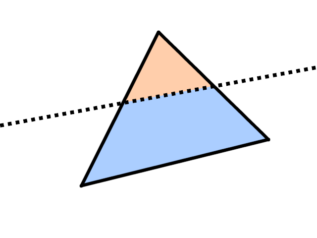
Case 3: one vertex is in the allowed region, leaving a small triangle
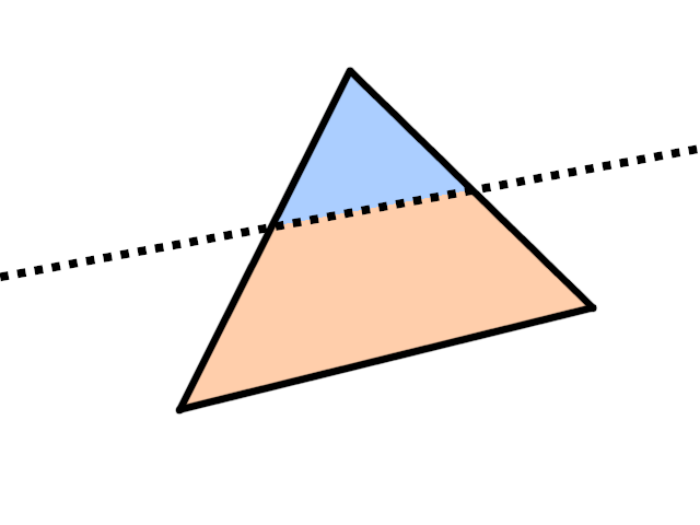
Case 4: two vertices are in the allowed region, leaving a quadrilateral
So, given a single linear equation (or, rather, inequality) of the form
\[ f(P) = A\cdot X+B\cdot Y+C\cdot Z+D\cdot W > 0 \]the algorithm for clipping a triangle by this equation is is:
- Determine the sign of the function \(f\) at the vertices of the triangle
- Depending on how many vertices are in the allowed region \(f(P)>0\), determine the case from the list above
- In case \(f(P)\leq 0\) for all vertices, skip the triangle
- In case \(f(P)> 0\) for all vertices, don't change the triangle
- In case \(f(P)> 0\) for one vertex, find the intersection of the two neighbouring triangle edges with the subspace \(f(P)=0\) and output a single triangle
- In case \(f(P)\leq 0\) for one vertex, find the intersection of the two neighbouring triangle edges with the subspace \(f(P)=0\) and output a quadrilateral split into two new triangles
Now, we actually have not one, but two equations (or six, if you include clipping by X and Y). That's not a problem: just clip them recursively!
One triangle clipping can produce two triangles at most, so clipping by two equations produces at most 4 triangles — not that big of a deal. Clipping by 6 eequations, however, can produce up to \(2^6=64\) triangles, which starts to sound problematic! Thankfully, I'm not using the full 6 equations here, just the two for Z.
Clipping a triangle: the Sutherland-Hodgman way
There is a slightly better, though also slightly more complicated, algorithm for doing the same thing, called the Sutherland-Hodgman algorithm. It differs from our algorithm in that it doesn't re-triangulate the clipping result up until the very end. Instead, it notices that a triangle is a flat convex polygon, and clipping such a polygon can only produce another flat convex polygon. To describe such a polygon, it is enough to specify the sequence of vertices in some order.
Given such a polygon, we can find all vertices that are in the disallowed region; due to convexity, they will all end up on one side, forming a consecutive subsequence. Then, we remove these vertices, and replace them with two new vertices formed by the intersection of two edges with the \(f(P)=0\) subspace, like in our previous algorithm. Here's a picture:
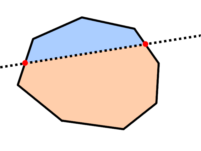
Red are newly-added vertices.
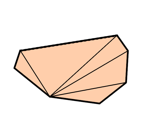
In this algorithm, for each equation we either don't change the polygon, or we remove at least 1 vertex and add 2 more vertices. Thus, in the worst case we add 1 more vertex with each clipping operation, giving a total of \(N+3\) vertices when clipping with \(N\) different equations, which can be further re-triangulated in a triangle fan of \(N+1\) triangles, starting from any vertex:
So, this algorithm works better when clipping with many equations, but it is a bit more complicated to implement, due to working with a circular array of vertices, and handling continuous subsequences of such a circular array. This is easier than it sounds, but it definitely requires some care.
As I've said, I'm only clipping with 2 equations \(-W < Z < W\), so I've decided to go with the simpler & more straightforward algorithm.
Clipping a triangle: implementation
Enough talking, let's write some code already. First, we'll represent a linear equation to clip by
\[ A\cdot X+B\cdot Y+C\cdot Z+D\cdot W > 0 \]Simply by the vector \(N = (A,B,C,D)\). Then, the equation can be rewritten as
\[ N \cdot P > 0 \]where \(P=(X,Y,Z,W)\) is a 4D point (e.g. a triangle vertex in homogeneous coordinates), and \(\cdot\) is a 4D dot product. Let's implement this dot product, by the way:
...

inline float dot(vector4f const & v0, vector4f const & v1)
{
    return v0.x * v1.x + v0.y * v1.y + v0.z * v1.z + v0.w * v1.w;
}

...
That was rather straightforward. Now, let's prepare our rasterizer code for some clipping. Recall that our vertices have some attributes: right now it's just the color, but in the future we'll have more of them. When clipping a triangle and generating new vertices, we'll need to compute the new attributes as well.
To simplify this, let's create a new vertex struct which will represent a vertex together with all its attributes. I'll put it inside the renderer.cpp file inside an anonymous namespace, because that's the only file that will need this new struct:
...

namespace rasterizer
{

    namespace
    {

        struct vertex
        {
            vector4f position;
            vector4f color;
        };

    }

}

...
Now, when iterating over the input triangles for rendering, we'll convert the vertices to this vertex struct, and then we need to clip them. We know that clipping a triangle by 2 equations creates at most 4 triangles, so we'll get at most \(4\times 3=12\) vertices after clipping a single input triangle.
I will implement clipping in-place, meaning that the clipping routine will replace the source array of vertices of an input triangle with the vertices of the clipping result.
Then, we need to iterate over the triangles resulting from clipping, and proceed with our usual rasterization stuff. Here's how it looks in code:
...

for (std::uint32_t vertex_index = 0; vertex_index + 2 < command.mesh.count; vertex_index += 3)
{
    std::uint32_t i0 = vertex_index + 0;
    std::uint32_t i1 = vertex_index + 1;
    std::uint32_t i2 = vertex_index + 2;

    if (command.mesh.indices)
    {
        i0 = command.mesh.indices[i0];
        i1 = command.mesh.indices[i1];
        i2 = command.mesh.indices[i2];
    }

    // Fill just 3 vertices, but leave place
    // for the clipping result
    vertex clipped_vertices[12];

    clipped_vertices[0].position = command.transform * as_point(command.mesh.positions[i0]);
    clipped_vertices[1].position = command.transform * as_point(command.mesh.positions[i1]);
    clipped_vertices[2].position = command.transform * as_point(command.mesh.positions[i2]);

    clipped_vertices[0].color = command.mesh.colors[i0];
    clipped_vertices[1].color = command.mesh.colors[i1];
    clipped_vertices[2].color = command.mesh.colors[i2];

    // This is where actual clipping takes place
    auto clipped_vertices_end = clip_triangle(clipped_vertices, clipped_vertices + 3);

    for (auto triangle_begin = clipped_vertices; triangle_begin != clipped_vertices_end; triangle_begin += 3)
    {
        auto v0 = triangle_begin[0];
        auto v1 = triangle_begin[1];
        auto v2 = triangle_begin[2];

        v0.position = perspective_divide(v0.position);
        v1.position = perspective_divide(v1.position);
        v2.position = perspective_divide(v2.position);

        v0.position = apply(viewport, v0.position);
        v1.position = apply(viewport, v1.position);
        v2.position = apply(viewport, v2.position);

        // Do the rasterization
        ...
    }
}

...
I'm making heavy use of the classic C++ style of working with iterator ranges (in this case, iterators are just pointers to an array).
Now we only need to implement the clip_triangle function. We have two equations for clip with: \(-W < Z\) and \(Z < W\). These correspond to the following equation vectors:
In the clip_triangle function, for each equation, we iterate over the triangles of the input array (specified by begin and end pointers), and clip them with this equation, outputting the result to a temporary result array. Then, we copy the vertices back from the result array to the original array (knowing that there is enough space for it).
Initially, begin..end stores just 3 vertices, but after the first clipping it can be 6 vertices forming 2 triangles, so in the loop we always assume that the begin..end array can contain more than one triangle.
We need to put the result to a temporary array and copy it back, because if we outputted directly to the array defined by the begin pointer, the clipping result could rewrite other triangles. Imagine that we had a single input triangle, and after clipping by the first equations we got two triangles t1 and t2, so that the begin..end array contains 2 triangles (6 vertices) [t1, t2]. Then, when clipping by the second equation, triangle t1 turns into two new triangles t3 and t4, and if we were to output directly into the same array, the array would be replaced by [t3, t4], and t2 would be lost.
I'm putting this function in the same anonymous namespace, together with struct vertex:
...

vertex * clip_triangle(vertex * begin, vertex * end)
{
    static vector4f const equations[2] =
    {
        {0.f, 0.f,  1.f, 1.f}, // Z > -W  <=>   Z + W > 0
        {0.f, 0.f, -1.f, 1.f}, // Z <  W  <=> - Z + W > 0
    };

    vertex result[12];

    for (auto equation : equations)
    {
        auto result_end = result;

        for (vertex * triangle = begin; triangle != end; triangle += 3)
            result_end = clip_triangle(triangle, equation, result_end);

        end = std::copy(result, result_end, begin);
    }

    return end;
}

...
But we're not done yet. This function is just a high-level part of the clipping that handles multiple equations and multiple resulting triangles, but in essence it is just two for loops. The real meat is in the clip_triangle(triangle, equation, result_end) function that clips a single triangle by a single equation.
It takes a pointer to the first vertex of an input triangle, the vector specifying a 4D linear equation, and a pointer to the array where the results will go. It returns a pointer to one-past-the-last generated vertex, — again, as is common when writing C++ algorithms, — so that the caller knows how many triangles were generated.
First, we compute the value of the equation \(N\cdot P\) at the three input triangle vertices. Then, we check if they are below or above zero, and form a mask telling us which particular clipping case we're working with.
...

vertex * clip_triangle(vertex * triangle, vector4f equation, vertex * result)
{
    float values[3] =
    {
        dot(triangle[0].position, equation),
        dot(triangle[1].position, equation),
        dot(triangle[2].position, equation),
    };

    std::uint8_t mask =
          (values[0] < 0.f ? 1 : 0)
        | (values[1] < 0.f ? 2 : 0)
        | (values[2] < 0.f ? 4 : 0);

    switch (mask)
    {
        ...
    }

    return result;
}

...
There are 2 possible signes at each of the 3 vertices, thus there are only 8 cases to consider. They can probably be groupped nicely, but I simply hard-coded each of the 8 cases separately. For example, the case mask = 0b110 means that vertices \(V_1\) and \(V_2\) are outside the allowed region, meaning that we need to keep vertex \(V_0\) and find two intersections of edges \(V_0V_1\) and \(V_0V_2\) with our equation, and output a triangle formed by \(V_0\) and these 2 new vertices:
...

switch (mask)
{
...
case 0b110:
    // Vertices 1 and 2 are outside allowed half-space
    // Replace them with points on edges 10 and 20
    *result++ = triangle[0];
    *result++ = clip_intersect_edge(triangle[1], triangle[0], values[1], values[0]);
    *result++ = clip_intersect_edge(triangle[2], triangle[0], values[2], values[0]);
    break;
    break;
...
}

...
The *result++ operation outputs a single vertex to the result, and advances the result pointer.
Here, the clip_intersect_edge function computes the intersection of an edge with the subspace \(f(P)=0\). Because our equation is linear, this function only needs the value of \(f(P)\) at the vertices, which we've already computed at the beginning of the function.
For another example, the case mask = 0b001 means that the vertex \(V_0\) is outside of the allowed range, so we compute two new vertices on edges \(V_0V_1\) and \(V_0V_2\), and output the quadrilateral formed by these new vertices together with \(V_1\) and \(V_2\), re-triangulating it at the same time:
...

switch (mask)
{
...
case 0b001:
    // Vertex 0 is outside allowed half-space
    // Replace it with points on edges 01 and 02
    // And re-triangulate
    {
        auto v01 = clip_intersect_edge(triangle[0], triangle[1], values[0], values[1]);
        auto v02 = clip_intersect_edge(triangle[0], triangle[2], values[0], values[2]);
        *result++ = v01;
        *result++ = triangle[1];
        *result++ = triangle[2];
        *result++ = v01;
        *result++ = triangle[2];
        *result++ = v02;
    }
    break;
...
}

...
You can see all the remaining cases on github, they are similar to the ones we've discussed.
Finally, the function clip_intersect_edge simply computes the point \(P\) on an input edge such that \(f(P) = 0\) and interpolates attributes. We know that a point on an edge \(V_0V_1\) can be represented as \(P=V_0 + t\cdot (V_1-V_0)\). Since our function is linear, we have
Solving for \(f(P) = 0\), we obtain
\[ t = \frac{f(V_0)}{f(V_0) - f(V_1)} \]This parameter \(t\) allows us to compute the position and other attributes of the resulting vertex using linear interpolation:
vertex clip_intersect_edge(vertex const & v0, vertex const & v1,
    float value0, float value1)
{
    float t = value0 / (value0 - value1);

    vertex v;
    v.position = (1.f - t) * v0.position + t * v1.position;
    v.color = (1.f - t) * v0.color + t * v1.color;

    return v;
}
And this was the final piece! With all this in place, we should have triangle clipping working correctly.
That's quite a lot of code, so let's recap what just happend:
- We have a function
clip_intersect_edgewhich computes the intersection of a triangle edge with a subspace \(f(P)\) — this will be a new vertex of a triangle generated by the clipping procedure. - We have a function
clip_triangle(triangle, equation, result), which computes the result of clipping a single triangle by a single equation. It handles 8 possible cases (whether vertices are inside or outside the allowed region), and uses the functionclip_intersect_edgeto compute new vertices. - We have a function
clip_triangle(triangle_begin, triangle_end), which computes the full clipping of an input triangle by two equations \(-W < Z\) and \(Z < W\). It does this in-place, outputting the result to the same array that contained the input. We know that clipping one triangle can produce at most 4 triangles, so we leave an array of 12 vertices for the result. - In our rendering engine, we clip each input triangle into several new triangles, and then rasterize these clipped triangles as usual.
Clipping a triangle: testing
Let's check that what we've written actually works. As before, let's render a cube, but put the camera in the center of it (i.e. don't translate the cube). Don't forget to disable face culling: from inside the cube, all the cube faces will be oriented clockwise, and will be culled if you set cull_mode = cull_mode::cw. We don't want cull_mode = cull_mode::ccw either, because we want to test clipping itself, and culling might obscure the result.
So, we do this in our main rendering loop:
matrix4x4f model = matrix4x4f::rotateZX(time) * matrix4x4f::rotateXY(time * 1.61f);

matrix4x4f projection = matrix4x4f::perspective(0.01f, 10.f, M_PI / 3.f, width * 1.f / height);

draw(color_buffer, viewport,
    draw_command{
        .mesh = cube,
        .transform = projection * model,
    }
);
and we should get
Now that definitely looks like we're inside the cube!
Let's do another test: move the cube a bit away from the camera, and set the near clip value to the center of the cube. This time, also set the face culling to CCW mode, because some overlapping might occur, and we still want to see the inside of the cube:
matrix4x4f model = matrix4x4f::translate({0.f, 0.f, -4.f})
    * matrix4x4f::rotateZX(time)
    * matrix4x4f::rotateXY(time * 1.61f);

matrix4x4f projection = matrix4x4f::perspective(4.f, 10.f, M_PI / 3.f, width * 1.f / height);

draw(color_buffer, viewport,
    draw_command{
        .mesh = cube,
        .cull_mode = cull_mode::ccw,
        .transform = projection * model,
    }
);
We should get something that looks like a cube cut in half via a random plane passing through the center of the cube:
Hooray! We have triangle clipping, now that's something.
Perspective-correct interpolation: the problem
The next 3D-specific problem we need to fix is related to textures. Wait, we don't have textures in our engine yet! — you might object. Ok, fine, the problem itself is a problem of attribute interpolation, but it is much more apparent when applying textures to 3D objects.
Since we don't support textures (yet), we'll cheat a bit, and hard-code a simple texture that illustrates the problem. Make a usual flat square with 4 vertices, and move it a bit in front of the camera:
vector3f positions[]
{
    {-1.f, -1.f, 0.f},
    { 1.f, -1.f, 0.f},
    {-1.f,  1.f, 0.f},
    { 1.f,  1.f, 0.f},
};

vector4f colors[]
{
    {0.f, 0.f, 0.f, 1.f},
    {1.f, 0.f, 0.f, 1.f},
    {0.f, 1.f, 0.f, 1.f},
    {1.f, 1.f, 0.f, 1.f},
};

std::uint32_t indices[]
{
    0, 1, 2,
    2, 1, 3,
};

matrix4x4f model = matrix4x4f::translate({0.f, 0.f, -2.f});

matrix4x4f projection = matrix4x4f::perspective(0.01f, 10.f, M_PI / 3.f, width * 1.f / height);

draw(color_buffer, viewport,
    draw_command{
        .mesh = {
            .positions = {positions},
            .colors = {colors},
            .indices = indices,
            .count = 6,
        },
        .transform = projection * model,
    }
);
(Note that I've set near clip plane back to 0.01, and removed culling.)
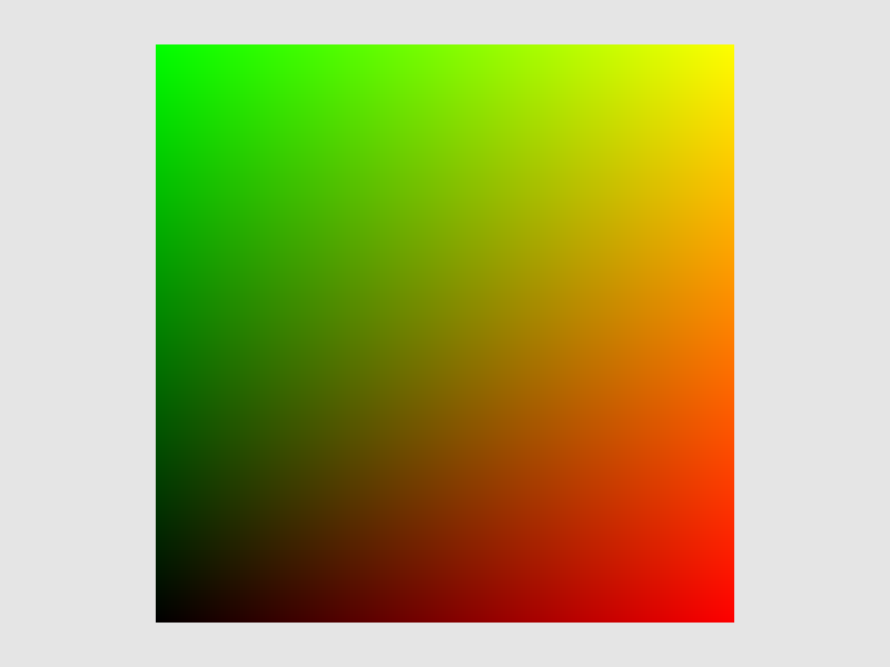
Now, to emulate a texture, replace the final pixel output command with some code that fills the object in a checkerboard pattern, based on the original color's red and green channels:
// This is what this code looked like before
// color_buffer.at(x, y) = to_color4ub(l0 * v0.color + l1 * v1.color + l2 * v2.color);

auto color = l0 * v0.color + l1 * v1.color + l2 * v2.color;

if (int(std::floor(color.x * 8) + std::floor(color.y * 8)) % 2 == 0)
    color_buffer.at(x, y) = {0, 0, 0, 255};
else
    color_buffer.at(x, y) = {255, 255, 255, 255};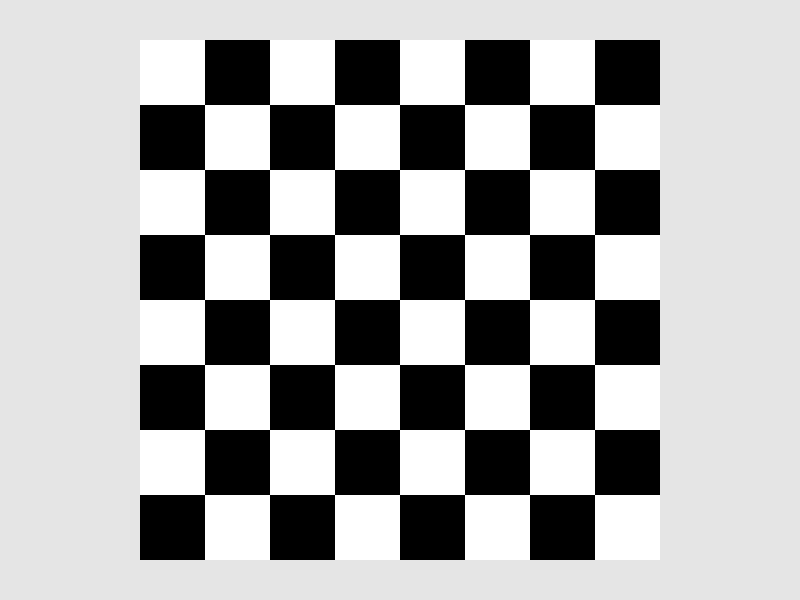
Here comes the fun part: start rotating the square around the X axis (i.e. in the YZ plane):
matrix4x4f model = matrix4x4f::translate({0.f, 0.f, -2.f})
    * matrix4x4f::rotateYZ(time);
The texture is wiggling left and right like crazy! And since the texture is based solely on the interpolated pixel color, it means that the colors are also doing that thing (but it would've been harder to notice than with a checkerboard). What's going on?
Perspective-correct interpolation: the math
The problem is that we're interpolating attributes (in this case, colors) in screen space, after performing the projection. Perspective projection preserves lines, but it doesn't preserve relative distances: if a point was exactly in the center between two other points, this won't be true in general after perspective projection. A bit more math-y way to phrase that is that perspective projection doesn't preserve linear combinations.
Some resources simply say that perspective projection doesn't preserve distances, but this is a bit misleading: the projection matrix, or even an affine scaling or shearing matrix dont't preserve distances as well. What we're really interested here is how different points on a line are related to each other: matrices always keep these relations (i.e. linear combinations), but perspective divide can break them.
Let's see this effect in formulas explicitly. Say, we have two clip-space points \(P_0=(X_0,Y_0,Z_0,W_0)\) and \(P_1=(X_1,Y_1,Z_1,W_1)\). Again, we're working in clip space, because all operations prior to that were matrix operations (including scaling, translation, rotation, and the projection matrix, but not the perspective divide), meaning that relations like "being in the middle of two points" are preserved up until now.
The clip-space middle between these points is simply \(\frac{1}{2}(P_0+P_1)\). The X-coordinate of this point is \(\frac{1}{2}(X_0+X_1)\), the W-coordinate is \(\frac{1}{2}(W_0+W_1)\), and after perspective divide we get \(\frac{X_0+X_1}{W_0+W_1}\).
To compute the screen-space middle of them, we need to apply perspective projection first, and only then do the averaging. So, the X-coordinates of the projected points will be \(\frac{X_0}{W_0}\) and \(\frac{X_1}{W_1}\), and the screen-space middle will be \(\frac{1}{2}\left(\frac{X_0}{W_0}+\frac{X_1}{W_1}\right)\). It is clear that in general
\[ \frac{X_0+X_1}{W_0+W_1} \color{red}{\neq} \frac{1}{2}\left(\frac{X_0}{W_0}+\frac{X_1}{W_1}\right) \]i.e. the projected middle is not the same as the middle of two projections.
This explains the texture squishing we've seen earlier: interpolating things in screen-space simply doesn't give us the result we would get by interpolating in the original space (which would be the correct thing to do). But we can't interpolate in the original space (e.g. in clip space): we don't have the coordinates of a 4D point in a triangle, we only have pixel coordinates!
To try and save the day, let's actually try to figure out which world-space (or clip-space, doesn't matter) point corresponds to the screen-space interpolation between points \(P_0\) and \(P_1\). I will use \(s\) for the screen-space interpolation parameter, and \(t\) for the world-space (or clip-space) interpolation patameter. Say, we're drawing a line (we'll get to triangles later) between the screen-space projections \(Q_0\) and \(Q_1\) of points \(P_0\) and \(P_1\), and we're currently rasterizing some pixel \(Q\) of this line. Somehow we've figured out the interpolation parameter \(s\) such that our current pixel is a linear interpolation between the two endpoints:
\[ Q = (1-s)Q_0 + sQ_1 \]Which clip-space point \(P\) on the line between \(P_0\) and \(P_1\) projects to this point \(Q\)? We know it must be on this line, since perspective projection preserves lines. A generic point on the line segment \(P_0P_1\) must have the form \(P = (1-t)P_0 + tP_1\). It's X-coordinate is \((1-t)X_0+tX_1\), W-coordinate is \((1-t)W_0+tW_1\), which after perspective divide becomes \(\frac{(1-t)X_0+tX_1}{(1-t)W_0+tW_1}\). But we also want this to be equal to the screen-space coordinates of \(Q\), which is a linear interpolation between \(Q_0\) and \(Q_1\), which in turn are results of applying perspective division to \(P_0\) and \(P_1\). This gives us an equation
\[ \frac{(1-t)X_0+tX_1}{(1-t)W_0+tW_1} = (1-s)\frac{X_0}{W_0}+s\frac{X_1}{W_1} \]It might look intimidating, but after multiplying both sides by \((1-t)W_0+tW_1\) it becomes linear in \(t\) and is actually quite easy to solve. Just grab all coefficients together, everything cancels out, and we're left with a nice and clean
\[ t = \frac{sW_0}{sW_0+(1-s)W_1} \]Let's check our intuition. Say, \(s=\frac{1}{2}\), i.e. we're interested in the screen-space middle of the two points. If \(P_0\) is close to camera (\(W_0\) is small), while \(P_1\) is really-really far away (\(W_1\) is large), we expect the screen-space middle between them to still be something that is relatively close to camera. Remember: perspective projection makes distant things small, so for far away objects more space fits into the same amount of pixels. The formula above gives us \(t\) being small (because it is something small divided by something large), which agrees with intuition: small \(t\) means a point close to \(P_0\), i.e. close to camera.
Let's now compute the W-coordinate of this point:
\[ W = (1-t)W_0 + tW_1 = \frac{(1-s)W_1W_0}{sW_0+(1-s)W_1} + \frac{sW_0W_1}{sW_0+(1-s)W_1} = \frac{W_0W_1}{sW_0+(1-s)W_1} \]This doesn't seem useful just yet, but let's rewrite it in terms of \(\frac{1}{W}\):
meaning that
\[ \frac{1}{W} = \frac{sW_0+(1-s)W_1}{W_0W_1} = (1-s)\frac{1}{W_0} + s\frac{1}{W_1} \]i.e. the inverse W-coordinate of our point is exactly the screen-space interpolation of inverse W-coordinates of the endpoints! To phrase it differntly: the inverse W-coordinate is linear in screen-space after perspective division.
This doesn't solve our problem just yet. We want to interpolate arbitrary attributes, and we don't really care about W after perspective division happened. The X-coordinate can be seen as one of the vertex attributes, and it changes linearly in world-space (for trivial reasons: \(f(X,Y,Z)=X\) is indeed a linear function). Let's compute the X-coordinate of our new point:
\[ (1-t)X_0+tX_1 = \frac{(1-s)W_1}{sW_0+(1-s)W_1}X_0 + \frac{sW_0}{sW_0+(1-s)W_1}X_1 = \frac{(1-s)W_1X_0 + sW_0X_1}{sW_0+(1-s)W_1} \]Dividing both the numerator and the denominator by \(W_0W_1\), we get
\[ (1-t)X_0+tX_1 = \frac{\frac{1-s}{W_0}X_0 + \frac{s}{W_1}X_1}{\frac{1-s}{W_0} + \frac{s}{W_1}} \]This might look really weird, but this is actually the solution to our problem! If we were to ignore the perspective division problems, the screen-space interpolation of two values looks simply like \((1-s)X_0+sX_1\). However, to deal with perspective projection, this formula tells us to do the following: divide the original weights \(1-s\) and \(s\) by the W-coordinates of the endpoints, use them as the linear interpolation coefficients \(\frac{1-s}{W_0}X_0 + \frac{s}{W_1}X_1\), then divide by \(\frac{1-s}{W_0} + \frac{s}{W_1}\). This last division can be seen as a normalization step, since we simply divide by the sum of the new weights (so that the weights effectively sum to \(1\)).
Now, nothing in our last derivation depended on X actually being the X-coordinate! We can plug colors, texture coordinates, normals, any attribute here, and the interpolation formula stays the same. And since the formula is still a linear combination but with tweaked weights, all we need is to, well, tweak them, and we can use the tweaked weights in all our attribute interpolation code verbatim.
But that's for a line segment. What do we do with a triangle? Well, simply rename \(\lambda_0 = 1-s\) and \(\lambda_1 = s\) and look at our formula once again:
\[ \frac{\frac{\lambda_0}{W_0}X_0+\frac{\lambda_1}{W_1}X_1}{\frac{\lambda_0}{W_0}+\frac{\lambda_1}{W_1}} \]From here we can either build an interpolation inside a triangle as two consecutive interpolations on a line segment (one gives a point \(P\) on the edge \(P_0P_1\), the second gives a point inside the triangle on the edge \(PP_2\)), or we could simply use the method of GUESSING and arrive at the formula for the triangle:
\[ \frac{\frac{\lambda_0}{W_0}X_0+\frac{\lambda_1}{W_1}X_1+\frac{\lambda_2}{W_2}X_2}{\frac{\lambda_0}{W_0}+\frac{\lambda_1}{W_1}+\frac{\lambda_2}{W_2}} \]As you can see, it's literally the same thing: take the original interpolation weights \(\lambda_i\), divide by the corresponding W-coordinates, normalize the resulting weights by dividing by their sum, and you're golden.
Notice how we only need to tweak the interpolation coefficients, and these same coefficients work for any vertex attribute. So, we don't need to worry about properly interpolating each separate attribute; rather, we tweak the interpolation weights, and these weights work correctly for any attribute.
Perspective-correct interpolation: the code
That was, once again, a ton of math. Thankfully, the fix in the code is really just a few lines! Do this in our interpolation coefficients computing code:
float l0 = det12p / det012 / v0.position.w;
float l1 = det20p / det012 / v1.position.w;
float l2 = det01p / det012 / v2.position.w;

float lsum = l0 + l1 + l2;

l0 /= lsum;
l1 /= lsum;
l2 /= lsum;
and we should finally get properly interpolated attributes:
Notice how the checkerboard isn't distorted anymore, and looks pretty much how we'd expect it to look. And, once again, notice that we've only tweaked the weights l0, l1, l2, and we didn't touch the code that interpolates colors later.
Now, in my code I did things ever so slightly differently. My perspective_divide function actually returns the inverse of the original W-coordinate in the W-coordinate of the result, for two reasons:
- This kinda mimicks some graphics APIs, e.g. in OpenGL the fragment shader built-in
gl_FragCoord.wis exactly the screen-space interpolated value of \(\frac{1}{W}\) - This serves as a tiny optimization since it precomputes the inverses \(\frac{1}{W_i}\)
The only change that is required further with my approach is that division by position.w turns into multiplication (since it is now the inverse of what we wanted to divide by):
float l0 = det12p / det012 * v0.position.w;
float l1 = det20p / det012 * v1.position.w;
float l2 = det01p / det012 * v2.position.w;
Of course, you can use whichever option you prefer. Directly dividing by W sounds like a more readable and understandable option, though.
Now that we have these new interpolation coefficients, we can use them to interpolate any vertex attribute, which we will use extensively a bit later.
This part was rather math-heavy; the next one will be a breeze, I promise :)
| \(\leftarrow\) Part 4: Changing perspective | Source code for this part | Part 6: Adding some depth \(\rightarrow\) |